Real-time Hybrid Simulation (RTHS) Implementation
Using NI PXI System
Large-scale dynamic experiments are essential to understand the system level dynamic behaviour of complex structures equipped with load-rate dependent components. However, such tests are very costly and their numbers can be minimized by performing an array of real-time hybrid simulations (RTHSs) that couple physical testing of critical components (i.e., experimental substructure) with the computer model of the remaining structure (i.e., analytical substructure). While it is economical and practical, RTHS is a challenging testing method since it combines computer simulation with physical testing in real-time. Successful application of RTHS requires robust and real-time executable algorithms, accurate control of the hydraulic actuators and synchronized data communication.
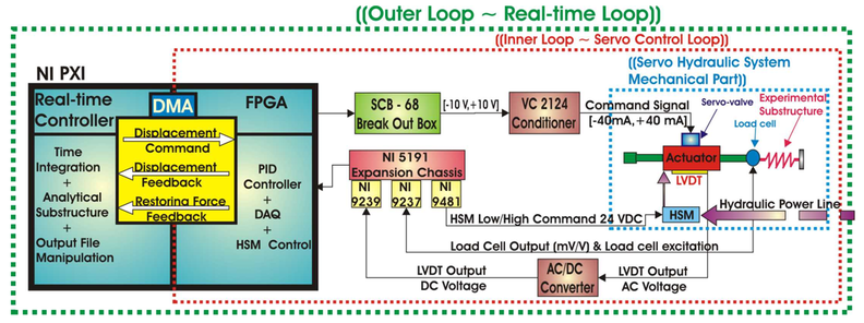
To address the computational and control challenges of RTHS, a flexible control/computational platform using National Instruments (NI) PXI system with FPGA (Field Programmable Gate Array) was devised. Unlike the previous implementations of the real-time hybrid simulation where turn-key standard controllers were used to control the actuators, this platform came with a generic controller that needed to be programmed by the user. Therefore, all the functionalities of the controller (safe start-up, emergency shut-down logics, servo-hydraulic control law) as well as the RTHS specific algorithms (integration algorithm and analytical substructure model) were programmed.
Software Development |
All the tasks for the successful implementation of RTHS were first partitioned to be programmed on the PXI Real-time and FPGA sides of the NI PXI system. FPGA is an integrated circuit designed to be configured by the user. The use of FPGA-based design and execution of the servo-loop control laws directly on the hardware provided high reliability, high determinism, true parallelism, and instant boot-up capabilities to the inner loop. Another advantage of this platform was that the synchronization between the inner loop (i.e the servo-hydraulic control loop on the FPGA) and outer loop ( the integration algorithm and the analytical substructure algorithms on the PXI-Real time) was established digitally using DMA (Direct Memory Access) option of the LabVIEW. This eliminated the use of a fiber optic device (i.e., SCRAMNet) which was used in the previous RTHS set-up for synchronous communication of inner and outer loops.
To enable the implementation of these software tasks, a NI LabVIEW programming architecture, namely a "State Machine" was employed. The state machine has distinguishable states where a state for a given task can lead to one or multiple states depending upon the user input or in-state calculations to determine which state to go to next. This allows interaction with the user while executing the programmed tasks. For example, at any instant the user can press the "Stop" button on the front panel (i.e., the user interface) of the controller, and in the background, the state machine will execute the relevant states to keep the actuator piston at the current position and de-energize the Hydraulic Service Manifold (HSM) high and low pressure solenoids to safely shut down the hydraulic system. Each state of the state machine was programmed as a separate LabVIEW code with the proper front panel components for the user interface. Only the integration and analytical substructure state determination algorithms were programmed in MATLAB Simulink, they were then converted into dynamic link library (.dll) files and executed from within LabVIEW program using Simulation Interface Toolkit. 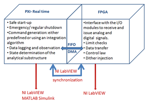
|
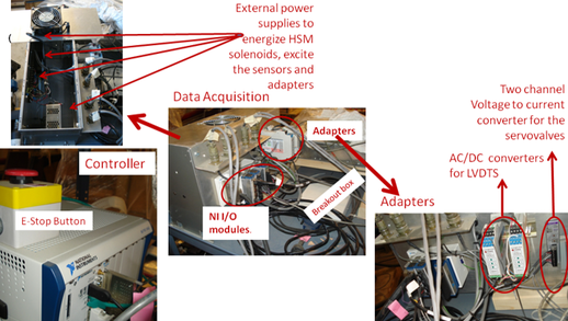
Hardware Configuration |
Since National Instrument controllers are not typically used to control servo-hydraulic actuators, there were several hardware compatibility issues which needed to be resolved. These include:
|
Experimental Verification |
To check all the functionalities of the user-reconfigurable computational control platform developed, a series of experiments were carried out. In Figure (a) a linear spring is being loaded by a single actuator, in Figure (b) two individual linear springs are being loaded by two actuators, and in Figure(c) the two actuators are physically coupled through the loading beam that can rotate about the hinge. These three set-ups were used to first check the inner loop functionalities. Specifically, the user defined control law programmed on the FPGA was shown to have accurate tracking capability in controlling (a) a single actuator (b) two uncoupled actuators, (c) two physically coupled actuators. Then, the outer loop RTHS functionalities (i.e., the integration algorithm and analytical substructure calculations) of the platform were verified using set-ups (a) and (b), where the linear springs were the experimental substructures. During the RTHSs a three story nonlinear analytical substructure was modelled on the PXI, and its response was coupled with one or both of the springs in real-time. Since the experimental substructures were linear, it was possible to generate a true solution numerically; and verify the accuracy of the RTHS results.
Reference: Ashasi-Sorkhabi and Mercan (2014) 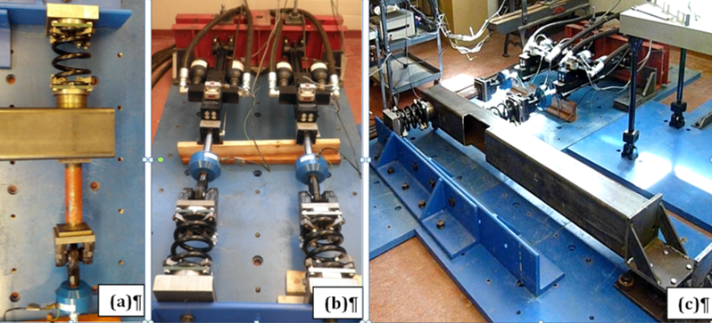
|