The UT-SIM framework consists of mainly three components: 1) communication modules, 2) integration modules, and 3) substructure modules. Complete with a standardized communication protocol and data exchange format, communication modules allow seamless communication between different software. For dynamic problems, integration modules are the main integration software that runs numerical time integration to solve the system’s equation of motion. Substructure modules provide the integration modules with restoring forces of the structural components (critical subdomain) whose behaviour needs to be simulated (numerically modelled or physically tested) in detail. The current development of the UT-SIM framework enables two types of decomposition methods (component-level decomposition and system-level decomposition).
Consider a large structural system whose equation of motion can be expressed as:
$Ma+Cv+R=F$
where $M$ and $C$ are the system's mass and damping matrices; $R$ and $F$ are restoring force and external load vectors; $a$ and $v$ are acceleration and velocity vectors, respectively. Depending on the structural components' properties, $R$ can be displacement-dependent $R(d)$, velocity-dependent $R(v)$ (e.g., viscous dampers), or both displacement- and velocity-dependent $R(d,v)$ (e.g., base isolators). The notion of structural decomposition in the UT-SIM framework is more general than that for the conventional substructuring methods in the sense that decomposition does not necessarily have to be performed along geometric boundaries but can also be performed on the mathematical terms, $M$, $C$, and $R$ in the above equation of motion. There are mainly two methods to decompose the equation. For the sake of simplicity, it is assumed that a system is decomposed into two substructures □ and □, which are independently modeled in analysis modules X and Y, respectively.
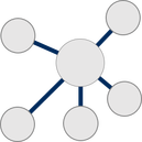
Component-Decomposition
In this method, decomposition is only made for the damping and/or restoring forces of the system. Then, the equation of motion becomes:
$Ma+C_iv_i+C_jv_j+R_i+R_j=F$
where the subscripts $i$ and $j$ denote the terms relevant to substructure $i$ and $j$, respectively. The figure below illustrates the way to model the substructures with the analysis module X and Y. Including the inertial properties and the external load of the entire system, module X acts as the main solver of the equation of motion in addition to the computations of the damping and restoring forces for substructure $i$. Analysis module Y, on the other hand, only works as a slave to the module X and its main task to determine $C_jv_j$ and $R_j$ and provide them to the analysis module X. This method has been mostly used in the hybrid simulation testing to properly capture the nonlinear hysteretic behaviour of the critical subdomain of a structure and consider their influence on the global structural response. The analysis module Y can be either a sophisticated numerical model or a physical specimen. In the UT-SIM framework, the integration and substructure modules work as the X module and Y module, respectively.

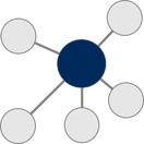
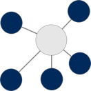
System-Level Decomposition
In this method, decomposition is not only made for damping and/or restoring forces but also for the inertial properties of the system.
$M_ia_i+M_ja_j+C_iv_i+C_jv_j+R_i+R_j=F_i+F_j$
The modelling of the two substructures with the analysis modules X and Y is shown below. Different from the component-level decomposition approach, this method equally treats both substructures and dynamic integrations are performed in both X and Y modules. This method is also known as the domain-decomposition method, which are aimed to capture dynamic interactions between different physical fields or domains. In the UT-SIM framework, the integration modules are used for the modelling of the decomposed dynamic substructures. More details about this approach can be found in Huang and Kwon (2020).

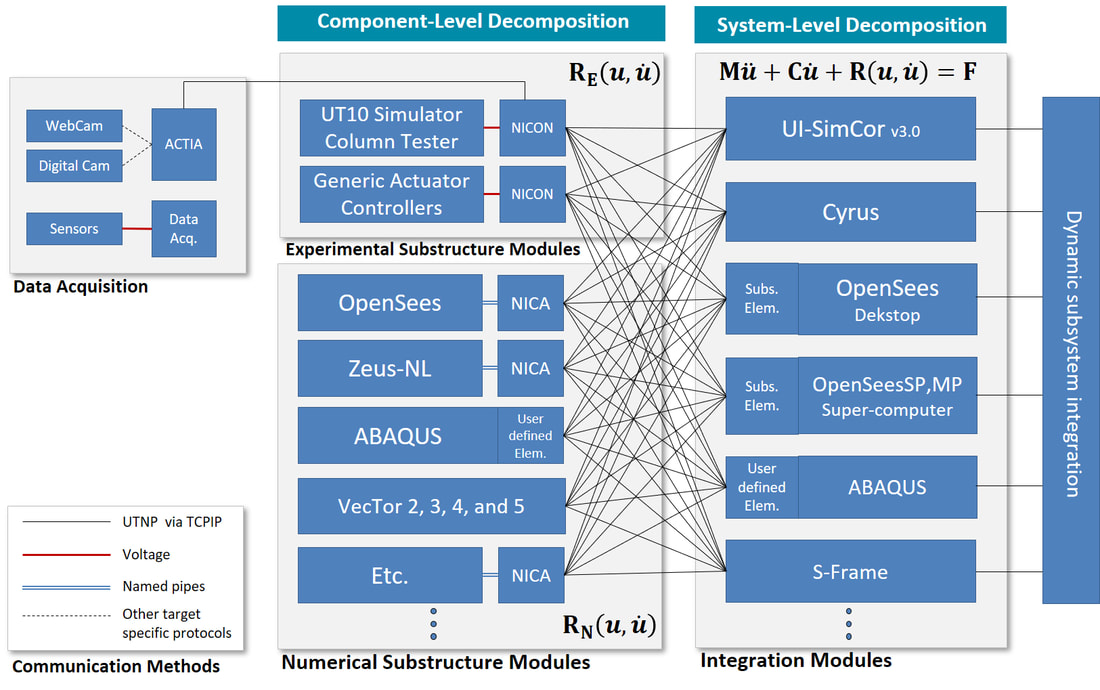
Communication ProtocolThe standardized communication protocol and data exchange format are the main components that allow for the seamless integration of diverse software and physical specimens. At this stage, an extensible data exchange format and a simple communication protocol is developed. Currently improvements are being made on the communication protocols to reduce the lag during geographically distributed communication. Analog voltage signals are used for the communication between the software and actuator control systems, because most controller system support such functionalities.
|
Integration Modules
An integration modules is a main Integration modules are software tools which run a numerical time integration scheme for a dynamic problem or serve as main solvers in static problems. Thus, an integration module is used to model the majority of the structural system. Substructure modules, on the other hand, include components that need to be modeled as physical specimens or sophisticated finite elements in other software packages. In network communications, the integration module acts as a client while substructure modules act as servers. Depending on the nature of the problems, one of the following integration modules can be used for hybrid or multi-platform simulations.
|
Substructure ModulesSubstructure modules include models of relatively small regions in a structural system that need to be modeled in great detail. For example, one may want to model a link beam with detailed finite element models (or even physical specimens) while the rest of the structural system can be modeled with frame elements. At this stage, all substructure modules are assumed to be static modules which are rate-independent. There are a few examples of methods which allow for the integration of dynamic subsystems to other dynamic systems, but such algorithms are not yet mature for general application to nonlinear dynamic problems.
|
The above architecture applies to the Real Time Hybrid Simulations (RTHS). In RTHS, however, the real-time synchronization of the numerical analysis and experimental test is one of the most important requirements. Thus, it is necessary to develop the integration modules, substructure modules, and even actuator controllers such that all these components can be perfectly synchronized with minimal delay in each time step. With this purpose, a real-time controller and FPGA based real time simulation method has been developed.