OverviewThe UT-SIM framework can be used to run pseudo-dynamic or real-time hybrid (experiment-analysis) simulation. Pseudo-dynamic hybrid simulation is preferable if the physical specimen's hysteretic behaviour is rate-independent or if it is necessary to use sophisticated numerical models which cannot be analyzed in real-time. Real-time hybrid simulation is suitable for evaluating the performance of a structure with rate dependent elements, such as viscous dampers, and a computationally efficient structural model primarily due to computational requirement.
The main components to run hybrid simulations are listed below:
|
|
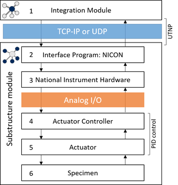
The overall architecture of the hybrid simulation is very similar regardless of whether it is a real-time or pseudo-dynamic hybrid simulation but there are several different approaches depending on how the architecture is implemented. For example, in many real-time hybrid simulations, modules #1 thorough #3 (or sometimes #4) are all combined as a single module to minimize the communication time lag. Two different methods have been used for the communication between the module #3 and #4: analog voltage input/output or SCRAMNet. More details on the connectivity of the integration module to the actuator controller are discussed below:
1. Integration module |
The integration module runs a numerical time stepping method. The UT-SIM framework does not specify that any one program be used as the main integration module. Rather, any integration module following the communication protocol can be used as the main program. At the current stage, UI-SimCor, OpenSees, Cyrus, and S-Frame can all be used as the main integration module. The current version of the UT-SIM framework is primarily for pseudo-dynamic hybrid simulation. Currently the UT-SIM team is trying to extend the framework for geographically distributed real-time simulations by improving communication protocols, and by developing an integration module in real-time hardware.
|
2. NICON |
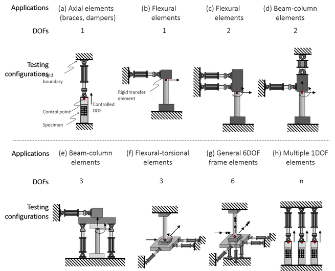
One of the essential tasks in hybrid (analysis-experiment) simulation is to establish communication between an actuator controller and a numerical integration module. In addition, if multiple actuators are used to control coupled degrees of freedoms (DOF) of a specimen (such as a column under axial and lateral forces and moment), the displacement commands in the numerical model’s Cartesian coordinate system need to be transformed to actuators’ strokes and feedback displacements, and forces need to be converted back to the model’s Cartesian coordinate system. This conversion requires iteration due to the geometric nonlinearity of the testing setup. Establishing the communication and enabling the coordinate transformation for hybrid simulation are not trivial tasks for a testing facility that is new to the simulation method. To facilitate the adoption of a hybrid simulation method in a conventional structural testing facility, a generalized controller interface program has been developed based on LabView and National Instrument’s hardware. The interface program, called the Network Interface for Controllers (NICON), receives commands from the network based on a standardized data exchange format (UTNP), converts coordinate systems, generates analog voltage commands to actuator controllers, and returns measured responses. The program is generalized so that it can be used for various configurations of testing setups such as single DOFs, three coupled DOFs, six coupled DOFs, and ten uncoupled DOFs. Validation tests have been carried out using multi-axial testing apparatus at the University of Toronto.
|
3. NI Hardware |
In the UT-SIM framework, NICON allows communication between an integration module and actuator controller. UTNP is used for the communication between the integration module (#1) and NICON (#2). For the communication between NICON (#2) and actuator controller (#3), it was decided to use analog I/O through hardware from National Instruments. The main reason of this approach are; 1) most actuator controllers can accept commands from external sources through analog signals, and output measured values through analog signals. This approach requires a D/A and A/D conversion process, but the time lag from the conversion process is negligible. In some studies, the analog signals have been used in real-time hybrid simulations as well. 2) the hardware to generate and read analog signals is generally inexpensive. Unless real time processing is required, generic voltage input and output modules can be purchased for a few thousand dollars. It was confirmed that analog I/O can be used to command and to get measurements from the controllers of the following vendors: MTS, Shore Western, and Instron.
Some controllers include SCRAMNet cards such that an integration module and the actuator controller can directly access same memory address, which is used as a means of communication. This approach, however, requires proprietary SCRAMNet cards and controllers, which could be quite costly. The following image shows an NI hardware (CompactRIO), which is wired to the Shore Western Controller. Because the setup is intended to control a 6DOF system, the setup requires 6 channels of input to the controller, 6 channels of displacement output, 6 channels of force output, and additional channels to take measurements of a specimen externally. A similar setup is currently used for all other pseudo-dynamic hybrid simulations at University of Toronto. 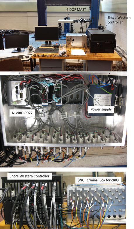
|
4. Actuator Controllers |
Actuator controllers run a PID control loop based on displacement or force feedback. In some real-time hybrid simulations, the actuator control loop is modified to minimize the time lag coming from the physical system (actuator-specimen). In pseudo-dynamic hybrid simulations, the lag is not an issue. As long as the actuators can impose the target displacement up to a certain level of accuracy, the controller can be used for hybrid simulations.
The most common limiting factor is usually the flexibility of the reaction system. Most actuators use their internal LVDT as a displacement feedback signal, which is not the actual deformation of the specimen. The actual deformation of the specimen is influenced by the relative stiffness of the specimen and the reaction system. Thus, in many tests, the actual specimen's deformation needs to be externally measured, and then used as a displacement feedback. This approach is somewhat dangerous if a specimen fails abruptly, or if there is any chance that debris such as spalling concrete hits the LVDT. In many previous tests, the external feedback is used to run one more layer of external control loop (i.e. updating comment in Module #2 to Module #4). |
5. Actuators |
The majority of the structural testing equipment is operated with hydraulic power. Depending on the number of DOFs, the equipment may consist of a single actuator or many actuators acting simultaneously. In the Structural Testing Facility at University of Toronto, several unique pieces of equipment are available, all of which can be fully integrated into hybrid simulations using the UT-SIM framework. This technical know-how is open to the research community. All the necessary software and hardware specifications will be posted on this website. The following is some of the equipment that can be integrated in hybrid simulations.
|
UT10 Simulator |
UT10 Simulator has been developed to test up to ten uni-axial specimens, such as braces and friction/yielding dampers in a hybrid manner. The UT10 Simulator consists of a loading frame, servo controlled hydraulic jacks, and control programs. The UT10 Simulator can test up to ten specimens with ±800 kN force capacity, or up to five specimens with ±1,600 kN capacity. Interface program, NICON, is used to interface the controller program with an integration software.
|
Shell Element Tester |
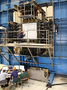
The Shell Element Tester, utilized for studying the behaviour of very large reinforced concrete elements subjected to in-plane and out-of-plane forces, was initially designed in 1984 under the direction of Professor M. P. Collins and Professor P. Marti. The testing facility is unique in various aspects. It is the only facility of its kind capable of testing full scale shell elements subjected to all 8 possible force components. This piece of equipment houses 60 hydraulic jacks, 40 in-plane, which have a capacity of 1000 kN, and 20 out-of-plane, which have a capacity of 500 kN. Specimens up to 1.5 m square by 0.4 m thick can be accommodated. The SET can be used to apply bending, shear and torsional loading to regular and high-strength reinforced concrete elements, and has been used to test components of nuclear power plants and concrete offshore structures. In 2009 this piece of equipment was dramatically upgraded by equipping each of the 60 jacks with servovalves, string pots and a high-end digital controller. Recently, the controller of the SET was upgraded to feed up to 16 channels of external commands, which can be as a command source for hybrid simulation.
|
Column Testing Frame |
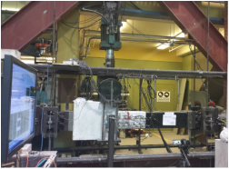
This specially constructed frame houses a 9,000 kN hydraulic jack for the application of axial loads and a 1,000 kN servo-controlled actuator for the application of transverse loads. The frame is being upgraded such that it can serve as a column hybrid simulator.
|
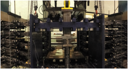
6DOF Testing Machine |
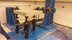
The six-DOF shaking table is equipped with three 2 kip actuators in horizontal direction and three 3 kip actuators in vertical direction. The equipment is used to understand the effect of multi-axial loading on dynamic response of structures. In addition, the equipment also can be used as a static multi-axial loading equipment for pseudo-dynamic hybrid simulations.
|
Uniaxial Shaking Table |
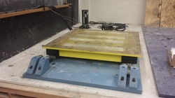
The uni-axial shake table has capacity of 1 ton of payload at 1 g of acceleration.
|